Inner ring
The Đdmp,△Bs of Sl…E,SI…ES,SA…E,SA…ES,SIR…ES,SIQ…ES,SK…ES,SF…ES,SI…C,SA…C,SI…ET-2RS,SA…ET-2RS are same as radial spherical plain bearings GE…E,GE…ES,GE…C,GE…ET-2RS
The △dmp,△Bs of SIGEW…ES are same as radial spherical plain bearings GEEW…ES.PHS…,POS…,PHSB…,POSB…,PHS…EC,POS…EC,PHS…HD,POS…HD,NPHS…,NPOS…,SPHS…,SPOS…,SPHS…EC,SPOS…EC,SCHS…SCOS.
d mm | △dmp | △Bs | |||
Over | Incl. | max | min | max | min |
-- | 6 | +12 | 0 | 0 | -150 |
6 | 10 | +15 | 0 | 0 | -150 |
10 | 12 | +18 | 0 | 0 | -150 |
12 | 18 | +18 | 0 | 0 | -200 |
18 | 30 | +21 | 0 | 0 | -200 |
Center height deviation (mm)
d | △hs | △h1s | |||
Over | Incl. | max | min | max | min |
-- | 6 | +0.80 | -1.20 | +0.65 | -1.05 |
6 | 20 | +0.80 | -1.20 | +0.80 | -1.20 |
20 | 30 | +1.00 | -1.70 | +1.00 | -1.70 |
30 | 45 | +1.40 | -2.10 | +1.40 | -2.10 |
45 | 60 | +1.80 | -2.70 | +1.80 | -2.70 |
60 | 80 | +2.25 | -3.40 | +2.25 | -3.40 |
80 | 125 | +2.70 | -3.40 | +2.70 | -3.40 |
125 | 200 | +3.20 | -4.20 | +3.20 | -4.20 |
Tolerances for American size rod ends are indicated in each table enclosed.
Bearing internal clearance is defined as the total distance through which one ring can be moved radially (radial internalclearance)or axially (axial internal clearance)in relation to the other ring under a defined measuring load.
It is necessary to distinguish between the internal clearance of a bearing before it is mounted and the internal clearance of a mounted bearing when in operation (operational clearance).The initial clearance will always be greater than the operational clearance because the rings are expanded or compressed by interference fit and as a result of the differences in thermal expansion of the bearing rings and mating components.
The bearing internal clearance referred to as normal has been selected so that when bearings are mounted generally recommended and operate under normal conditions a suitable operational will be obtained. For other conditions,e.g.where both rings are mounted with an interference fit or where unusual temperatures prevail,bearing with greater or smaller internal clearance than normal may be required.
Radial internal clearance of steel-on-steel radial spherical plain bearings
Series of GE…E, GE…ES, GE…ES-2RS, GEEW…ES, GEEM…ES, GEZ…ES, GEZ…ES-2RS, COM.., COMH…, COM…SS, MIB,AIB,SIB
d mm | Group C2 μm | Group Normal μm | Group C3 μm | ||||
Over | Incl. | min | max | min | max | min | max |
-- | 12 | 8 | 32 | 32 | 68 | 68 | 104 |
12 | 20 | 10 | 40 | 40 | 82 | 82 | 124 |
20 | 35 | 12 | 50 | 50 | 100 | 100 | 150 |
35 | 60 | 15 | 60 | 60 | 120 | 120 | 180 |
60 | 90 | 18 | 72 | 72 | 142 | 142 | 212 |
90 | 140 | 18 | 85 | 85 | 165 | 165 | 245 |
140 | 200 | 18 | 100 | 100 | 192 | 192 | 284 |
200 | 240 | 18 | 110 | 110 | 214 | 214 | 318 |
240 | 300 | 18 | 125 | 125 | 239 | 239 | 353 |
Series of GEG…E, GEG…ES, GEG…ES-2RS
d mm | Group C2 μm | Group Normal μm | Group C3 μm | ||||
Over | Incl. | min | max | min | max | min | max |
-- | 10 | 8 | 32 | 32 | 68 | 68 | 104 |
10 | 17 | 10 | 40 | 40 | 82 | 82 | 124 |
17 | 30 | 12 | 50 | 50 | 100 | 100 | 150 |
30 | 50 | 15 | 60 | 60 | 120 | 120 | 180 |
50 | 80 | 18 | 72 | 72 | 142 | 142 | 212 |
80 | 120 | 18 | 85 | 85 | 165 | 165 | 245 |
120 | 160 | 18 | 100 | 100 | 192 | 192 | 284 |
160 | 220 | 18 | 100 | 100 | 192 | 192 | 284 |
220 | 280 | 18 | 110 | 110 | 214 | 214 | 318 |
Series of GEBK…S
d mm | Group C2 μm | Group Normal | μm | Group C3 μm | ||||
Over | Incl. | min | max | min | max | min | max | |
2.5 | 6 | 4 | 34 | 10 | 50 | 42 | 70 | |
6 | 10 | 5 | 41 | 13 | 61 | 52 | 88 | |
10 | 18 | 6 | 49 | 16 | 75 | 64 | 107 | |
18 | 30 | 7 | 59 | 20 | 92 | 98 | 150 | |
Series of GE…C,GE…PW,COM…T,COM…H,COMSS…H,WSSB.…,WSSB…V,NSSB.…,NSSW…V, YSSB…,YSSB.V,MIB…AIB…,SIB … .
d mm | Group Normal μm | ||
Over | Incl. | min | max |
-- | 12 | 4 | 28 |
12 | 20 | 5 | 35 |
20 | 30 | 6 | 44 |
Series of GE…ET-2RS, GE…XT-2RS
d mm | Group Normal μm | ||
Over | Incl. | min | max |
-- | 20 | 0 | 40 |
20 | 35 | 0 | 50 |
35 | 60 | 0 | 60 |
60 | 90 | 0 | 72 |
90 | 140 | 0 | 85 |
140 | 240 | 0 | 100 |
240 | 300 | 0 | 110 |
Series of GEG…ET-2RS,GEG…XT-2RS
d mm | Group Normal μm | ||
Over | Incl. | min | max |
-- | 30 | 0 | 50 |
30 | 50 | 0 | 60 |
50 | 80 | 0 | 72 |
80 | 120 | 0 | 85 |
120 | 220 | 0 | 100 |
220 | 280 | 0 | 110 |
Series of Sl…E,SI…ES,SA…E,SA…ES,SIR…RS,SIGEW…ES,SIQ…ES,SK…ES,SF…ES,CM …, CF…,,JM…,JML…JF…,JFL…,RJM…,RJF…ALJM…,ALJF…,ALRSM …
d mm | Group C2 μm | Group Normal μm | Group C3 μm | ||||
Over | Incl. | min | max | min | max | min | max |
-- | 12 | 4 | 32 | 16 | 68 | 34 | 104 |
12 | 20 | 5 | 40 | 20 | 82 | 41 | 124 |
20 | 35 | 6 | 50 | 25 | 100 | 50 | 150 |
35 | 60 | 8 | 60 | 30 | 120 | 60 | 180 |
60 | 90 | 9 | 72 | 36 | 142 | 71 | 212 |
90 | 125 | 9 | 85 | 42 | 165 | 82 | 245 |
125 | 200 | 9 | 100 | 50 | 192 | 96 | 284 |
Series of Sl…C,SA…C,SI…ET-2RS,SA…ET-2RS,CHS…,COS…,SCHS…,SCOS…,NPHS…,NPOS…PHS…EC,POS.EC,SPHS…EC,SPOS.EC,SPHSB…EC,SPOSB…EC,CF…T,CM…T,SCF…T,SCM…T,,CMX…T,RJM…T, RRSMX…T,SJM…T,SRSM…T,SJF…T,HJMX…T,PMX…T,NJF…,NJM…,NXF…,NXM…,NEXF…,NEXM…, NAF…,NAM…,RSM…T,RSMX…T,HRSMX…T
d mm | Group | C2 μm | Group Normal μm | Group C3 μm | |||
Over | Incl. | min | max | min | max | min | max |
-- | 12 | 0 | 25 | 0 | 32 | 15 | 45 |
12 | 20 | 0 | 30 | 0 | 40 | 20 | 60 |
20 | 35 | 0 | 35 | 0 | 50 | 25 | 65 |
35 | 60 | 0 | 40 | 0 | 60 | 30 | 80 |
60 | 80 | 0 | 50 | 0 | 72 | 35 | 90 |
Series of PHS…,POS…PHSB…,POSB…,PHS…HD,POS…HD,SPHS…,SPOS…,M…,F …
d mm | Group C2 μm | Group Normal μm | Group C3 μm | ||||
Over | Incl. | min | max | min | max | min | max |
2.5 | 6 | 2 | 34 | 5 | 50 | 21 | 72 |
6 | 10 | 3 | 41 | 7 | 61 | 26 | 88 |
10 | 18 | 3 | 49 | 8 | 75 | 32 | 107 |
18 | 30 | 4 | 59 | 10 | 92 | 39 | 120 |
30 | 50 | 5 | 71 | 13 | 112 | 49 | 150 |
Shaft fits
Operating conditions | Sliding contact surface of combination | |
Requiring maintenance | Maintenance-free | |
Loads of all kinds,clearance or transition fit | h6,hardened shaft | h6,g6 |
Loads of all kinds, interference fit | m6 | k6 |
Housing fit
Operating conditions | Sliding contact surface of combination | |
Requiring maintenance | Maintenance-free | |
Light loads,Axial displacement required | H7 | H7 |
Heavy loads | M7 | K7 |
Liaht alloy housings | N7 | M7 |
Shaft diameter tolerances
Shaft diameter mm | Shaft diameter tolerances μm | ||||||||
g6 | h6 | k6 | m6 | ||||||
Over | Incl. | High | Low | High | Low | High | Low | High | Low |
3 | 6 | -4 | -12 | 0 | -8 | +9 | +1 | +12 | +4 |
6 | 10 | -5 | -14 | 0 | -9 | +10 | +1 | +15 | +6 |
10 | 18 | -6 | -17 | 0 | -11 | +12 | +1 | +18 | +7 |
18 | 30 | -7 | -20 | 0 | -13 | +15 | +2 | +21 | +8 |
30 | 50 | -9 | -25 | 0 | -16 | +18 | +2 | +25 | +9 |
50 | 80 | -10 | -29 | 0 | -19 | +21 | +2 | +30 | +11 |
80 | 120 | -12 | -34 | 0 | -22 | +25 | +3 | +35 | +13 |
120 | 180 | -14 | -39 | 0 | -25 | +28 | +3 | +40 | +15 |
180 | 250 | -15 | -44 | 0 | -29 | +33 | +4 | +46 | +17 |
250 | 315 | -17 | -49 | 0 | -32 | +36 | +4 | +52 | +20 |
Housing bore tolerances
Housing bore diameter(mm) | Housing bore tolerances μm | ||||||||
H7 | K7 | M7 | N7 | ||||||
Over | Incl. | High | Low | High | Low | High | Low | High | Low |
10 | 18 | +18 | 0 | +6 | -12 | 0 | -18 | -5 | -23 |
18 | 30 | +21 | 0 | +6 | -15 | 0 | -21 | -7 | -28 |
30 | 50 | +25 | 0 | +7 | -18 | 0 | -25 | -8 | -33 |
50 | 80 | +30 | 0 | +9 | -21 | 0 | -30 | -9 | -39 |
80 | 120 | +35 | 0 | +10 | -25 | 0 | -35 | -10 | -45 |
120 | 180 | +40 | 0 | +12 | -28 | 0 | -40 | -12 | -52 |
180 | 250 | +46 | 0 | +13 | -33 | 0 | -46 | -14 | -60 |
250 | 315 | +52 | 0 | +16 | -36 | 0 | -52 | -14 | -66 |
315 | 400 | +57 | 0 | +17 | -40 | 0 | -57 | -16 | -73 |
400 | 500 | +63 | 0 | +18 | -45 | 0 | -63 | -17 | -80 |
Fits for rod ends
Shaft fits
Operating conditions | Tolerance |
With indeterminate loads | n6,p6 |
Normal conditions | h6,h7 |
Thread
Male Thread | Female Thread |
6g | 6H |
UNF-2A | UNF-2B |
BSF-free | BSF-normal |
Shaft diameter tolerances
Shaft diameter mm | Shaft diameter tolerances | ||||||||
h6 | h7 | n6 | p6 | ||||||
Over | Incl. | High | Low | High | Low | High | Low | High | Low |
3 | 6 | 0 | -8 | 0 | -12 | +16 | +8 | +20 | +12 |
6 | 10 | 0 | -9 | 0 | -15 | +19 | +10 | +24 | +15 |
10 | 18 | 0 | -11 | 0 | -18 | +23 | +12 | +29 | +18 |
18 | 30 | 0 | -13 | 0 | -21 | +28 | +15 | +35 | +22 |
30 | 50 | 0 | -16 | 0 | -25 | +33 | +17 | +42 | +26 |
50 | 80 | 0 | -19 | 0 | -30 | +39 | +20 | +51 | +32 |
80 | 120 | 0 | -22 | 0 | -35 | +45 | +23 | +59 | +37 |
120 | 180 | 0 | -25 | 0 | -40 | +52 | +27 | +68 | +43 |
180 | 250 | 0 | -29 | 0 | -46 | +60 | +31 | +79 | +50 |
Proper press-fitting of spherical bearings into a housing fixture will result not only in smooth bearing performance,but also in better wear characteristics leading to longer life. LDK engineering recommends strict adherence to the following installation procedures in order to assure optimal spherical bearing performance and wear.
The spherical bearings and rod ends must be kept in their original packaging until shortly before their installation,so that they continue to be effectively preserved for as long as possible.Ensure during the installation process that foreign particles are on no account allowed to enter the outer ring of the bearing.
The use of a hydraulic press to apply constant pressure is recommended.Any other shocking-inducing device such as a hammer will result in damage and/or ultimate misfit. An installation tool such as that shown on the left is ideal.Here the guide pin aligns the ball's bore parallel to the race O.D.,while all force is applied to the outer race surface only.The force required for installation and removal should on no account be transmitted from the spherical form to the bearing shells or raceways of the bearing outer ring.
Customers often require a bearing with a specially formed "V"-shaped groove on the face of the outer rave,allowing for staking of the bearing into bearing into a fixed outer housing. This is accomplished by forcing the metal on the outside of the groove onto the fixture's face or into its chamfer.The use of hydraulic press for this operation is recommended, as is following the instructions for the initial installation of the bearing into the housing as described above.
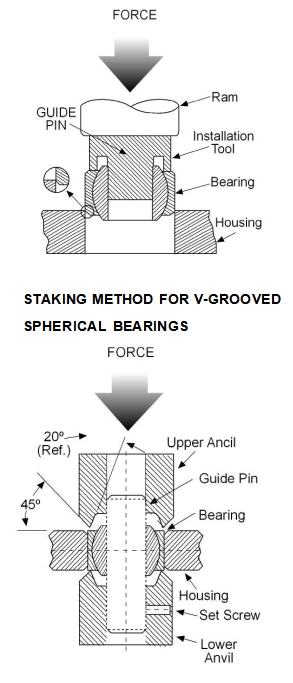
LDK Engineering recommends an upper and lower anvil method for installation.Anvils should be aligned as shown,with guide pin in position.This pin should ideally be secured in the lower anvil by means of a set screw.A test assembly should be undertaken to assure that required axial (thrust)load requirements of the final product are maintained.Avoid excessive pressure which can result in distortion leading to premature failure or malfunction.When the test requirements are met, the assembly should be rotated at 90°maximum intervals,with pressure re-applied,to assure uniformity of the metal swaging process.
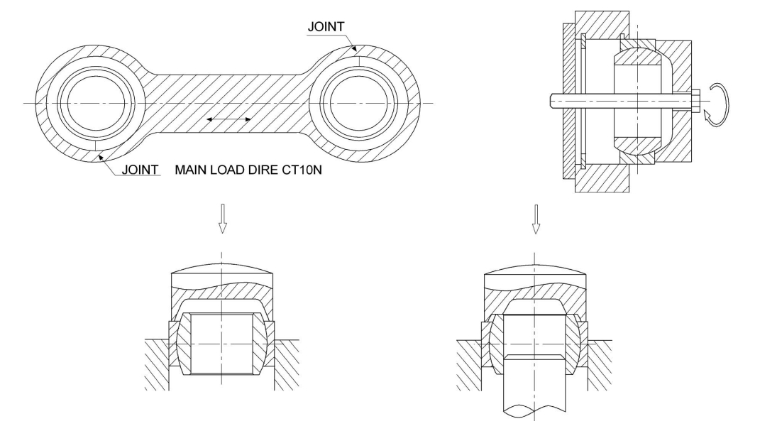
When mounting spherical plain bearings with a fractured or two-part outer ring,it is essential that the joint should be positioned at 90°to the main load direction,otherwise the service life will be shortened,particularly under heavy loads.
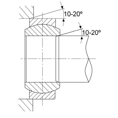
To facilitate mounting,the ends of pins or shafts and the edges of housing bores should have a lead chamfer of 10°to 20°,The bearings can be more easily pushed into position and there is little risk of damage to the mating surfaces being caused by skewing of the bearing.
The useful life of all spherical bearings and rod ends with metallic mating materials is greatly dependent on regular lubrication. A one-off initial grease filling is only adequate if operating loads are very low.
The effectiveness of lubrication is mainly dependent on the load,type of the load (constant,pulsating or alternating),the swivel and sliding speed.To ensure optimum and even distribution of the lubricant,initial and subsequent lubrication should be carried out with the spherical plain bearings or rod ends in an unloaded condition.
Note:
In order to avoid incompatibility of various lubricants that may be used by LDK and the customer,spherical bearings and rod ends are supplied only with an anti-corrosive coating.For this reason,spherical bearings and rod ends which need maintenance should be given initial lubrication before commissioning or directly after installation.We recommend carrying out-initial lubrication after a running-in time of approx 1 hour.Whenever this lubrication is carried out,the bearing must be in an unloaded condition,so that the lubricant can spread without obstruction.Lubrication should continue until the lubricant emerges between the bearing outer ring and the inner ring.For rod ends with a female thread,it is also advisable to fill the space in the shank thread with lubricant up to the threaded connection journal before installation.This reduces the amount of work involved in lubricating with the lubricating nipple.
For spherical plain bearings requiring maintenance which are of the steel-on-steel type,the purpose of the lubrication is primarily to reduce wear,reduce friction and prevent scuffing.Also the grease serves to protect the bearings against corrosion.The frequency of relubrication of the bearing during its operation will appreciably extend the service life.
For steel-on-PTFE fabric spherical plain bearings,there is a transfer of PTFE from fabric to the opposing steel surface of the inner ring.Any lubrication of the sliding contact surfaces would disturb this transfer and shorten bearing life.Therefore, lubrication of these bearings is not advisable.
For steel-on-PTFE composite material spherical plain bearings,as a rule,it must not be lubricated.When operating conditions are such that enhanced sealing and protection against corrosion are required,it is recommended that the bearing or the space surrounding the bearing is filled with lithium base grease.
LDK steel-on-steel and steel-on-bronze rod ends have very wear-resistant.Sliding surface and perform well under conditions of lubricant starvation.Rod end with this sliding contact surface combination requires regular relubrication. LDK maintenance-free rod ends sliding contact surfaces have two groups.Steel-on-PTFE composite and steel-on-PTFE fabric.They have very low friction and can be operated without maintenance.Therefore.Lubrication of these bearing is not advisable.

Catalog load ratings are based on rod ends without grease fittings.
For adjusted load ratings with grease fittings consult LDK engineering.
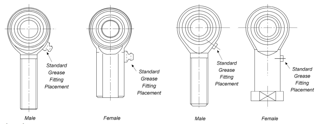
Location
Standard grease fitting locations are illustrated at the right.Note that for a female configuration,once the male threaded component is fully engaged,the grease is forced through the hole at the top of the female shank to facilitate ball lubrication.
Standard Grease Fitting
Order by adding the letter ''z'' to the completed number.example: CM8Z
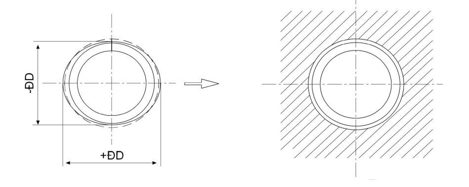
The tolerances apply to outer ring without surface treatment and splitting.The outer rings become slightly out of round due to splitting.The roundness of the outer ring is restored once it is fitted in a housing bore produced in accordance with the specifications (Figure1).Measurements taken of the outside diameter of the unfitted bearing cannot be used as
the original actual values for the outside diameter.
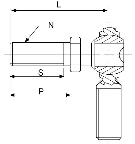
ROD END PART SIZE | L LGTH. | P LGTH. | S LGTH. | N THD. |
+.015 -.015 | REF. | MIN. | UNF 2A | |
3 | 1.016 | 500 | .437 | 10-32 |
4 | 1.031 | .562 | .500 | 1/4-28 |
5 | 1.219 | 687 | .593 | 5/16-24 |
6 | 1.562 | .906 | .812 | 3/8-24 |
7 | 1.750 | 1.062 | .937 | 7/16-20 |
8 | 2.000 | 1.125 | 1.000 | 1/2-20 |
10 | 2.500 | 1.500 | 1.375 | 5/8-18 |
12 | 3.000 | 1.812 | 1.625 | 3/4-16 |
NOTE:
AVAILABLE ON ALL SERIES.
SUTD MATERIAL:LOW CARBON STEEL AND ALLOY STEEL(HEAT TREATED) -ZINC PLATED.
STUD MISALIGNMENT APPROX. +/-25°IN ANY DIRECTION.
TO SPECIFY RIGHT HAND STUD, ADD SUFFIX"Y"TO PART NUMBER. EXAMPLE: CM6Y
TO SPECIFY LEFT HAND STUD, ADD SUFFIX "YL"TO PART NUMBER. EXAMPLE: CM6YX
TO SPECIFY HEAT TREATED STUD, ADD SUFFIX"YX"TO PART NUMBER. EXAMPLE: CM6YX
FOR LOAD RAINGS WITH STUDS,PLEASE CONTACT LDK ENGINEERING DEPARTMENT.
LDK warrants that the products well be free from defects in material and workmanship for one year from date of sale. LDK makes no other warranty of any kind,express or implied.LDK shall have no obligation under the foregoing warranty where the defect is the result of improper or abnormal use,negligence,vehicle accident,improper or incorrect installation or maintenance,nor when the product has been repaired or altered in any way so as (in our judgment)to affect its its performance. LDK's liability in the case of defective products subject to the foregoing warranty shall be limited to the repair or replacement, at LDK's option,of the defective products.Except expressly provide herein,LDK shall have no liability (on account negligence or otherwise)for,or in connection with,defects or deficiencies in the products and in no event shall LDK be liable for any incidental, special or consequential damages or commercial loss (including loss revenue or profits)of buyer or any other person,arising our of the use,or inability to use,the goods, or the failure or ineffectiveness of the goods.
LDK reserves the right to substitute equal or stronger materials at their discretion. LDK reserve the right to change specifications and other information included in this catalog without notice.All information,data and dimension tables in this catalog have been carefully complied and thoroughly checked.However,no responsibility for errors or omissions can be assumed.
WARNING
Since the manufacturer is unable to determine all applications in which a part may e placed, it's the user's responsibility to determine the suitability of the part of its intended use.This is especially true where safety is a factor.Incorrect application or installation may result in property damage,bodily injury,or death.For technical assistance, please check with us.
