3.3.1 Tolerances for Pressed Steel Pillow Block Type Housings
Tolerances for pressed steel pillow block type housings are shown in Table 23.
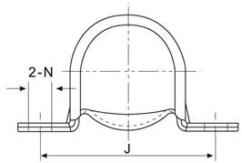
Table 23. (mm)
Housing No. | Deviation of mounting bolthole distance △J | Deviation of mounting bolt hole diameter △N | ||
high | low | high | low | |
PP203 PP204 PP205 PP206 PP207 PP208 PP209 | +0.40 | -0.40 | +0.50 | -0.50 |
3.3.2 Tolerances for Pressed Round and Oval Flange Type Housings.
Tolerances for pressed steel round and oval flange type housings are shown in Table 24.
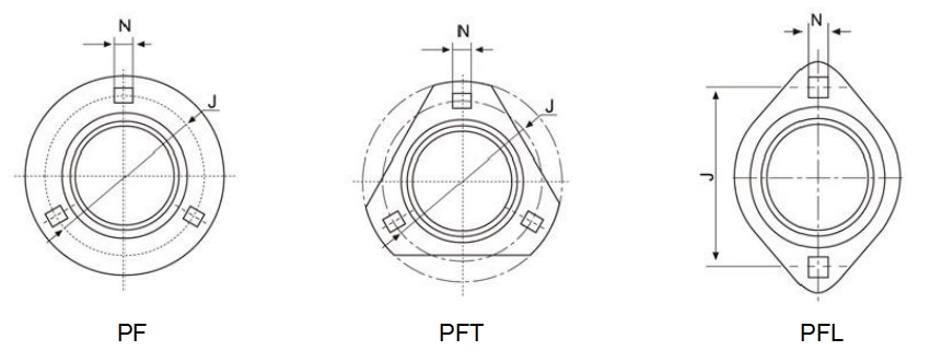
Table 24. (mm)
Housings No | Tolerances of position for mouting bolt holes △J | Deviation of length of square for mounting bolt holes △N | ||||
high | low | high | low | |||
PF203 PF204 PF205 PF206 PF207 PF208 PF209 PF210 PF211 PF212 | PFT203 PFT204 PFT205 PFT206 PFT207 PFT208 | PFL203 PFL204 PFL205 PFL206 PFL207 PFL208 | +0.40 | -0.40 | +0.25 | -0.25 |
The bearing size is usually selected according to the required bearing life and reliability under a specified type of load charged on the bearing.
The load applied to the bearing operating under a static or slow oscillating and rotating (n-10r/min)condition is defined as static load,while the load applied to the bearing operating under a speedy rotating(n>10r/min) condition is defined as dynamic load.
The load capacity of the bearing is expressed by the basic dynamic load rating and basic static load rating which is shown in the bearing table. (B120~B141)
Usually, the important factor of the selection of a rolling bearing is life calculation,which refers to fatigue life of the bearing.When bearing is under proper usage,appropriate load capacity,correct installation,good lubrication, the fatigue flake of rolling surface caused by alternating contact stress is the main element of bearing failure and this damage to the bearing can not be avoided completely.
Due to different application of each machinery and different requirement of the bearing,bearing could only be required to keep a certain kind of performance level during a specified period.After some time of working,factors like increased noise &vibration,declined precision caused by wear,grease aging will result in bearing failure or cannot satisfy the requirement of the machine.These type of life before bearing failure are called noise life,wear life and grease life.
Besides life,bearing failure may occur for the reason of burning,breakage,crack,seal failure etc which should be regarded as bearing malfunction.Bearing malfunction occurs because of improper selection of bearing, poor design of machinery,improper installation & usage and maintenance mistake which should be distinguished from bearing life.
Basic dynamic load rating:The basic dynamic load rating is defined as the constant load applied to a bearings with stationary outer rings that the inner rings can endure for a rating life of one million revolutions (106 rev.).
Life: The life of a rolling bearing is defined as the total number of revolutions which the bearing is capable of enduring before the first evidence of fatigue flaking develops on any one of the rings or rolling elements.
Reliability: The reliability is the percentage of the bearing of a group of apparently identical bearings operating under identical conditions which can expect to attain or exceed a certain defined life.The reliability of an individual bearing is the probability of the bearing to attain or exceed a defined life.
Basic rating life L10: For a group of apparently identical rolling bearings operating under identical conditions, the basic rating life is defined as the total number of revolutions that 90%of the bearings can be expected to complete or exceed.
The basic rating life L10 estimation for ball bearings with different speeds and ratios is shown in page A27~A28.
4.2.1 Basic Rating Life
The fatigue rating of deep groove ball bearings is calculated by following formula:
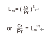
Where L₁₀=basic rating life (10⁶r)
Cr =basic dynamic load rating (N)
Pr =equivalent dynamic bearing load (N)
The basic dynamic load rating C is a hypothetical constant load with a fixed direction under which the bearing can attain basic rating life of one million revolutions.For radial bearing,the load refers to the radial load.
The equivalent dynamic bearing load P is a constant load with a fixed direction under which the bearing life is Identical to that of the bearing operating under actual load.
For a bearing operating with a constant rotation speed,the basic rating life can be expressed in terms of operating hours:
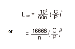
Where L10h=basic rating life (h)
n=bearing operating speed of rotation (r/min)
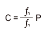
For easier calculation,500 hours as base of rating life is taken, And the speed factor fn and the life factor fn is introduced
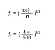
In this way, the formula is simplified to
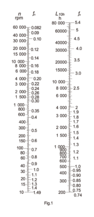
The values of fn and fn can be found in Fig.1 by referring to the operation speed n and the anticipated bearing service life L10h.Then,with the radial load (or the equivalent dynamic bearing load ), the basic dynamic load rating can be determined.By this way,the bearing size can be determined according to the basic dynamic load rating value in the bearings Table.(B120~B141)
If the bearing operates under indeterminate loads and rotation speed,the following formula should be applied when calculating the bearing life:

Where Pm =mean equivalent dynamic bearing load (N)
P=equivalent dynamic bearing load (N)
N =total revolution numbers within one load changing cycle (r)
4.2.2 Anticipated Bearing Service Life
When selecting a bearing,one should usually predetermine an appropriate service life according to the relevant machine type,operating conditions and reliability requirement.Generally speaking,the anticipated bearing
service life can be determined by referring to the maintenance period of a machine.
4.2.3 Calculation Method of Equivalent Dynamic Bearing Load P
The basic equivalent dynamic bearing load is determined under a hypothetical condition.When calculating the
Bearing life,the actual load has to be converted into equivalent dynamic bearing load which is in conformity with
the load condition determining the equivalent dynamic load rating.
General equation for calculating the equivalent dynamic bearing load:
P=X Fr+Y Fa
Where P=equivalent dynamic bearing load (N)
Fr = actual radial load (N)
Fa = actual axial load (N)
X = radial factor
Y = axial factor
The values of X and Y are determined by the ratio between the applied axial load Fa and the basic static load rating C0. The axial load which the spherical outside surface bearings can carry is determined by the mounting method of the bearing on the shafts.
For the setscrews locking type or eccentric locking collar type bearings,if flexible shafts are applied and the setscrews are tightened enough(See Table 38 on page A25 for reference torque),the axial load Fa which the bearing can carry must not surpass 20% of the radial load Fr.
For the adapter sleeve locking type bearing, if the nuts are properly tightened, the axial load Fa can be maximum 15% to 20%of the radial load.
The values of radial and axial factors X and Y for spherical outside surface ball bearings can be obtained from the following table:
Table 25

When twist load is applied to the bearings,the equivalent dynamic bearing load is calculated by:
Pm=fm·P
Where Pm=equivalent dynamic bearing load when considering twist load
Fm = twist load factor,which is defined as follows:
when the twist load is small: fm=1.5
when the twist load is big: fm =2
When shocking load is applied to the bearings,the equivalent dynamic bearing load can be calculated by the following equation:
Pd=fd·P
Where Pd=equivalent dynamic bearing load when considering shocking load
fd=shocking load factor,which is defined as follows:
When no shocking load or minor shocking load is applied:
fd=1~1.2
When adequate shocking load is applied;
fd=1.2~1.8
4.3 Example of bearing size selection
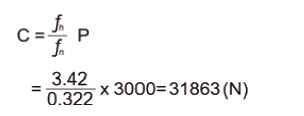
One ball bearing is to operate at a rotation speed of 1000 r/min under only a radial load of Fr=3000 N,with a basic rating life of at least 20000 hours,select the bearing size.
From the required rotation speed,it can be found that:
fn=0.322(Fig 1.shows about 0.32)
From the required basic rating life (anticipated service life), at least 20000 hours,it can be found that:
fn=3.42(Fig 1.shows about0.34)
Under only a radial load,i.e.,
P=Fr=3000(N)
Therefore,
A simplified way to calculate the bearing life can be applied by using Fig 2.
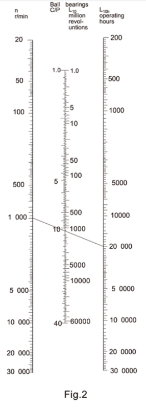
Life calculation chart
By connecting n(1000r/min)and the required basic rating life L10h(20000 hours)with a straight line,it can be
found that C/P value 10.6, As known,P=Fr=3000(N),thus the required basic dynamic load rating is:
![]()
C=10.6P
=10.6×3000=31800(N)
In this way, we can select the bearing from the bearing table (Please refer to page B120-B141)
The basic rating life L10 calculated with the bearing life calculation formula can be applied to calculate the rating life of bearing made of ordinary bearings steel (i.e.,bearing life with reliability of 90%.)
Due to more and more of machinery products demanding higher reliability and better quality steel,GB/T6391-1995(equaling to ISO281:1990)suggested an adjusted rating life calculation equation,i.e.,
Lna=a₁·a₂·a₃·L10
For the deep groove ball bearings:
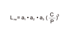
Where Lna=under specified material and lubricating conditions,bearing life with (100-n)% no breaking probability (i.e.reliability)
a₁=life adjustment factor for reliability(Table 26.)
a₂=life adjustment factor for materials (Table 27.)
a₃=life adjustment factor for operating conditions (Table 28.)
Table 26. Life adjustment factors for reliability a1
Reliability % | 90 | 95 | 96 | 97 | 98 | 99 |
Ln | L10 | L₅ | L₄ | L₃ | L₂ | L₁ |
a₁ | 1 | 0.62 | 0.53 | 0.44 | 0.33 | 0.21 |
Table 27. Life adjustment factors for materials a₂
Normal chromium bearing steel | a₂=1 |
Special smelted bearing steel-vacuum degassed bearing steel (a3≮1) | a₂>1 |
When material hardness lowered by high frequency tempering | a₂<1 |
Table 28. Life adjustment factors for operating conditions a₃
When under normal operating conditions,i.e.:Properly mounted; sufficiently lubricated;Without outside matters intrusion. | a₃=1 |
When under operating temperature,the ball bearing lubricating grease viscosity is lower than 13mm²/s. The bearing operating under lower speed Dpw•n<10000(mm·r/min ) Dpw =pitch circle diameter of rolling elements. | a₃<1 |
The industry lithium based N0.2 lubricating grease defined in GB7324 "Lithium based lubricant grease"is
filled the spherical outside surface ball bearings during manufacturing. Its physical and chemical properties
are shown in table 29.
Table 29.
Density (1/10mm) | Without operation | 265~295 |
Dropping point(℃) | ≥175 | |
Mechanical impurities (pc/cm³) | 10-25μm 25-75um 75-125μm above 125μm | Within 5000 Within 3000 Within 500 0 |
The bearings usually operate below the temperature of 120℃(the measuring temperature of the outer ring is 100 ℃).Grease life reduction has to be taken into account when the bearings continue to operate at a temperature above 70 ℃.The lowest operating temperature should not be lower than -20 ℃ .
For higher or lower temperature application, please consult us for further information.
Under normal operating condition,the grease should conform to the life of the bearings. Relubricatable type bearing units must be periodically greased to assure long life.
The greasing interval is dependent on the bearing running speed,operating temperatures and ambient conditions.
The following table shows the standard relubrication period.
Table 30.
dn Value | Cleanliness | Temperature | Greasing interval | |
℃ | 0F | |||
40,000 and below | Clean | -15~65 Up to 65~100 | +5~150 Up to 150~210 | 6 to 12 months 2 to 6 months |
Up to 40,00 ~70,000 and below | Clean | -15~65 Up to 65~100 | +5~150 Up to 150~210 | 2 to 6 months 1 month |
Any dn value | Dirty | Up to 65 Over 65 | Up to 150 Over 150 | 1 week.to 1 month 1 day to 2 weeks. |
Any dn value | Very Dirty | Any temp | Any temp | 1 day to 2 weeks. |
Any dn value | Exposed to water splashes | Any temp | Any temp | Every day |
The grease nipples supplied by LDK bearing units are classified as A type(straight),B type(type 45°)and C type (type 90°)made of brass,A3 steel.Grease nipple types for LDK standard bearing units are given in table 31.The availability of the grease nipple dimensions and designation to each type are M6xl,M8x1,M10x1,1/14-28UNF, NPT1/8 and G1/8, as given in table 32. If any other grease fitting is required,the customers are required to specify dimensions and designations.
Table 31. Grease nipple types for LDK standard bearing units
Housings No | Grease fitting type and dimension |
203~210 305~309 X05~X09 | A Type,M6x1 |
211~218 310~320 X10~X20 | A Type,M8x1 |
322-328 | A Type,M10x1 |
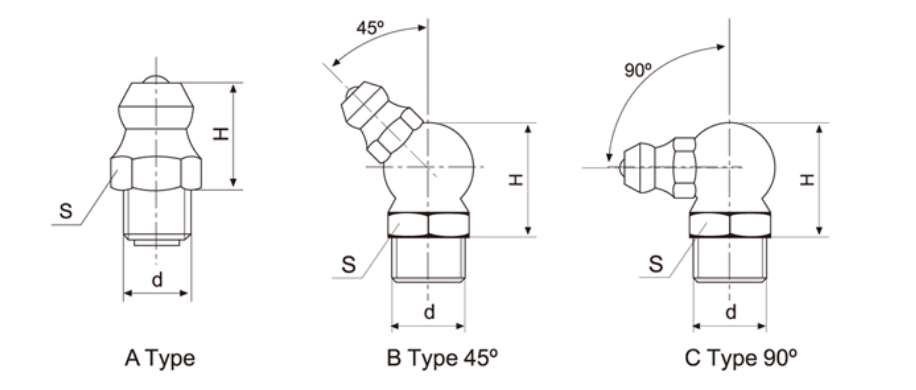
Table 32. Grease nipple dimensions and designations of applicable bearing units
Grease fitting Type | d | H(mm) | S(mm) |
A type | M6x1 | 8 | 7 |
M8x1 | 9 | 10 | |
M10x1 | 10 | 11 | |
1/4-28UNF | 8 | 7 | |
G1/8 | 10 | 11 | |
NPT1/8 | 10 | 11 | |
B type 45° | M6x1 | 15 | 10 |
M8x1 | 15 | 10 | |
1/4-28UNF | 15 | 10 | |
G1/8 | 15 | 11 | |
C type 90° | M6x1 | 15 | 10 |
M8x1 | 15 | 10 | |
1/4-28UNF | 15 | 10 | |
G1/8 | 15 | 11 |
The limiting speed of the ball bearing units are mainly determined by the fit between the bearings and the shafts.Under normal conditions,the fit for the setscrews type and eccentric locking collar type bearing unit is h7.h8 or h9 fit is applied when with light load and slow speed,while tighter fit j7 is applied when with heavy load and high speed.The shaft applied to the adapter sleeve bearing is h9 class,with IT5 class tolerances.
The speed ratings for ball bearing UD200(-2RS)series are the same as deep groove ball bearings which are shown in Table 33.
The limiting speeds for the ball bearing units with different fits are shown in Table 33.
Table 33. Limiting Speed (r/min)
d (mm) | 200 Series | 300 Series | CS200-2RS | ||||||
Shaft Tolerances | Shaft Tolerances | ||||||||
j7(h9/IT5) | h7 | h8 | h9 | 7(h9/IT5) | h7 | h8 | h9 | ||
12 | 6700 | 5300 | 3800 | 1400 | |||||
15 | 6700 | 5300 | 3800 | 1400 | 11000 | ||||
17 | 6700 | 5300 | 3800 | 1400 | 10000 | ||||
20 | 6000 | 4800 | 3400 | 1200 | 9000 | ||||
25 | 5600 | 4000 | 3000 | 1000 | 5000 | 3600 | 2600 | 900 | 8000 |
30 | 4500 | 3400 | 2400 | 850 | 4300 | 3000 | 2200 | 800 | 6700 |
35 | 4000 | 3000 | 2000 | 750 | 3800 | 2800 | 2000 | 700 | 6000 |
40 | 3600 | 2600 | 1900 | 670 | 3400 | 2400 | 1700 | 630 | 5600 |
45 | 3200 | 2400 | 1700 | 600 | 3000 | 2200 | 1500 | 560 | 5000 |
50 | 3000 | 2200 | 1600 | 560 | 2600 | 2000 | 1400 | 500 | 4800 |
55 | 2600 | 2000 | 1400 | 500 | 2400 | 1800 | 1300 | 450 | |
60 | 2400 | 1800 | 1200 | 450 | 2200 | 1700 | 1100 | 430 | |
65 | 2200 | 1700 | 1100 | 430 | 2000 | 1500 | 1100 | 400 | |
70 | 2200 | 1600 | 1100 | 400 | 1900 | 1400 | 1000 | 360 | |
75 | 2000 | 1500 | 1000 | 380 | 1800 | 1300 | 900 | 340 | |
80 | 1900 | 1400 | 950 | 340 | 1700 | 1200 | 850 | 320 | |
85 | 1800 | 1300 | 900 | 320 | 1600 | 1100 | 800 | 300 | |
90 | 1700 | 1200 | 800 | 300 | 1500 | 1100 | 750 | 280 | -= |
95 | == | 1400 | 1000 | 700 | 260 | ||||
100 | 1300 | 950 | 670 | 240 | |||||
105 | 1200 | 900 | 630 | 220 | |||||
110 | 1200 | 800 | 600 | 200 | |||||
120 | 1100 | 750 | 530 | 190 | |||||
130 | 1000 | 670 | 480 | 180 | |||||
140 | 900 | 600 | 430 | 160 | |||||
Note: The h9/IT5 column fit for adapter sleeve type ball bearing units,and the rest j7~h9 column fit for the setscrews type and eccentric locking collar type ball bearing units.
The ball bearing units are provided with two hexagonal setscrews 120° apart on one side of the inner rings. Under normal operating conditions, the inner rings are mounted on shafts by means of a loose fit to ensure convenience of installation.In this case, the dimensional accuracy of the shafts is shown in Table 34.
Table 34. Dimensional accuracy of the shafts to be used in the cylindrical bore bearings(Loose fit) (μm)
Shaft Diameter (mm) | Deviation of tolerance in shaft | ||||||||||
for lower speed | for medium speed | For rather high speed | for high speed | ||||||||
h9 | h8 | h7 | 6 | h6 | |||||||
over | incl. | max | min | max. | min | max | min | max | min | max | min |
10 18 30 50 80 | 18 30 50 80 120 | 0 0 0 0 | -43 -52 -62 -74 -87 | 0 0 0 0 0 | -27 -33 39 46 54 | 0 0 0 0 0 | -18 -21 -25 -30 -35 | +8 +9 +11 +12 +13 | -3 -4 -5 -7 -9 | 0 0 0 0 0 | -11 -13 -16 -19 22 |
When the ball bearing units are used at a high speed or under heavy load,the inner rings of the ball bearings
should be mounted to the shafts by means of a tight fit.As shown in Table 35.
Table 35. Dimensional accuracy of the shafts to be used in the cylindrical bore bearings(Tight fit) (μm)
Shaft Diameter (mm) | Deviation of tolerance in shaft | ||||||||
for higher speed | for rather heavy load | For highest speed | for heavy load | ||||||
m6 | m7 | n6 | n7 | ||||||
over | incl. | max | min | max | min. | max | min | max | min |
10 18 30 50 80 | 18 30 50 80 120 | +18 +21 +25 +30 +35 | +7 +8 +9 +11 +13 | +25 +29 +34 +41 +48 | +7 +8 +9 +11 +13 | +23 +28 +33 +39 +45 | +12 +15 +17 +20 +23 | +30 +36 +42 +50 +58 | +12 +15 +17 +20 +23 |
Some bearings can be installed to the shafts by means of adapter sleeves. In this method, the bearing bore is made of 1:12 taper and the corresponding tapered adapter sleeves are applied. This is a convenient method that can be used as the intermediate bearings of a long shaft. In this case,the dimensional accuracy of shafts is shown in Table 36.
Table 36. Dimensional accuracy of shafts to be used in tapered bore bearings (μm)
Shaft Diameter (mm) | Deviation of tolerance in shaft | ||||
for short shaft | for long shaft | ||||
h9 | h10 | ||||
over | incl. | max | min. | max. | min. |
10 18 30 50 80 | 18 30 50 80 120 | 0 0 0 0 0 | -43 -52 -62 -74 -87 | 0 0 0 0 0 | -70 -84 -100 -120 -140 |
Most industrial fans operate at high speeds.The inner ring of the ball bearing units should be mounted to
the shafts by means of h5 or j5 fit, As shown in table 37.
Table 37. Dimensional accuracy of shafts for HVAC industry (μm)
Shaft Diameter (mm) | Deviation of tolerance in shaft | ||||
h5 | j5 | ||||
over | incl. | max. | min | max | min |
18 30 50 80 | 30 50 80 100 | 0 0 0 0 | -9 -11 -13 -15 | +5 +6 +6 +6 | -4 -5 -7 -9 |
There are two setscrews located at two places on one side of the wide inner ring 120° apart with which the bearings can be mounted to the shafts.When mounting the bearings to the shafts,the torque shown in the table 38 is recommended to tighten the setscrews to shafts.
Table 38. Proper tightening torque of setscrews
Bearings No. | Setscrews (mm) | Tightening torque N•m(max) | Setscrews (in.) | Tightening torque 1bf•in(max) |
UC201~UC203 SB201~SB204 | M5X0.8 | 3.9 | 10-32UNF | 32 |
UC204~UC206 UC305~UC306 SB205~SB207 | M6X1 | 4.9 | 1/4-28UNF | 43 |
UC207~UC209 UC307 SB208~SB209 | M8X1 | 8.0 | 5/16-24UNF | 70.5 |
UC210~UC213 UC308~UC309 SB210~SB212 | M10X1.25 | 16.8 | 3/8-24UNF | 148 |
UC214~UC218 UC310~UC314 | M12X1.25 | 27.1 | 7/16-20UNF | 235 |
UC315~UC316 | M14X1.5 | 34.3 | 1/2-20UNF | 300 |
UC317~UC319 | M16X1.5 | 54.2 | 5/8-18UNF | 478 |
UC320~UC324 | M18X1.5 | 58.0 | 5/8-18UNF | 496 |
UC326~UC328 | M20X1.5 | 78.0 |
In case of either the vibration is caused to the bearing: or 1)the alternating movement takes place, 2)the load applied to the bearings is large, 3)The shafts rotation speed is rapid, it is desired to provide with the filed seat or concave section at the part where the setscrews contact with the shafts. As shown in Fig.3.

Fig.3
8.2 Adapter Sleeves Locking Type Bearings
The inner ring bore of this type of bearings has a taper of 1:12.The sleeves are installed to an arbitrary position.After the shake proof washers are inserted,the correct nuts tightening condition can be obtained if they are tightened enough by hand and then rotated by 2/5 to 3/5 revolution with a spanner.
After tightening the nuts,bend the shake proof washers within the slots. Otherwise,the nuts may loosen and creep may happen between the shaft and sleeves.
8.3 Eccentric Locking Collar Type Bearings
The eccentric part of the collars mates with the inner rings of the bearings which is made eccentric with the collars.When locked to the shafts by hand in direction of the shafts rotation,the eccentric locking collars tighten automatically to the shafts by force of working radial loads.Then,lock the setscrews provided on the collar to fix the eccentric collars to the shafts.
8.4 Mounting Method of Housings
The desired installation order is:first install the housing,then the shaft and bearing.The bearing units can be easily installed,in principle,at any place.However,in order to have a long
service life,it is desired that the mounting base is flat and rigid.

Fig.4.
The pillow block type and flange type housings are desired that the angle between the surface on which the housing is mounted and the shaft be maintained to a tolerance of±2°(Fig.5).
When there are shields or seals on the bearing housing,the slanted angle which is the angle between the central line of bearing bore and the central line of bearing housing bore is required within±1°

Fig.5.
8.5 Mounting Method of Take-up Units
The Take-up units are mounted on two parallel slides, bearing centers to be adjusted by adjustable bolts. The relevant parts dimensions are shown as Fig.6. Mounting tolerances are shown in Table 39 and Table 40.

Fig.6
Table 39. (mm)
Take-up No. | H' ±0.5 | A' | d | D | N |
T204 T205 T206 T207 T208 T209 T210 T211 T212 T213 T214 T215 T216 T217 | 77 77 90 90 103 103 103 131 131 152 152 152 167 175 | 11 11 11 11 15 15 15 20 20 24 24 24 24 28 | 16 16 18 18 24 24 24 30 30 36 36 36 36 42 | 28 28 32 32 42 42 42 56 56 60 60 60 60 65 | 12 12 12 12 14 14 14 20 26 26 26 26 26 30 |
Table 40. (mm)
Take-up No. | H' ±0.5 |
A' |
d |
D |
N |
ST204 | 77 | 12.5 | 16 | 28 | 12 |
ST205 | 77 | 12.5 | 16 | 28 | 12 |
ST206 | 90 | 12.5 | 18 | 32 | 12 |
ST207 | 90 | 12.5 | 18 | 32 | 12 |
ST208 | 103 | 16.5 | 24 | 42 | 14 |
ST209 | 103 | 16.5 | 24 | 42 | 14 |
ST210 | 103 | 16.5 | 24 | 42 | 14 |
ST211 | 131 | 25 | 30 | 56 | 20 |
ST212 | 131 | 25 | 30 | 56 | 26 |
Table 41.
L10h (hours) | Cr/Pr When speed n= (r/min) | |||||||||||||||
50 |
100 |
200 |
300 |
500 |
750 |
900 |
1000 |
1500 |
1800 |
2000 |
2500 |
3000 |
4000 |
5000 |
6000 | |
500 | 1.14 | 1.45 | 1.82 | 2.08 | 2.47 | 2.82 | 3.00 | 3.11 | 3.56 | 3.78 | 3.91 | 4.22 | 4.48 | 4.93 | 5.32 | 5.65 |
1000 | 1.44 | 18.2 | 2.29 | 2.62 | 3.11 | 3.56 | 3.78 | 3.91 | 4.48 | 4.76 | 4.93 | 5.31 | 5.65 | 6.21 | 6.70 | 7.11 |
1500 | 1.65 | 2.08 | 2.62 | 3.00 | 3.56 | 4.08 | 4.31 | 4.48 | 5.13 | 5.45 | 5.65 | 6.10 | 6.46 | 7.11 | 7.65 | 8.15 |
2000 | 1.82 | 2.29 | 2.88 | 3.30 | 3.91 | 4.48 | 4.76 | 4.93 | 5.65 | 6.00 | 6.21 | 6.69 | 7.11 | 7.81 | 8.43 | 8.96 |
3000 | 2.08 | 2.62 | 3.30 | 3.78 | 4.48 | 5.13 | 5.42 | 5.65 | 6.46 | 6.85 | 7.11 | 7.66 | 8.14 | 8.96 | 9.65 | 10.3 |
5000 | 2.47 | 3.11 | 3.91 | 4.48 | 5.32 | 6.08 | 6.46 | 6.70 | 7.66 | 8.14 | 8.43 | 9.09 | 9.65 | 10.6 | 11.5 | 12.2 |
7500 | 2.82 | 3.56 | 4.48 | 5.13 | 6.06 | 6.96 | 7.37 | 7.66 | 8.77 | 9.32 | 9.65 | 10.4 | 11.1 | 12.2 | 13.1 | 13.9 |
10000 | 3.11 | 3.91 | 4.93 | 5.65 | 6.70 | 7.66 | 8.14 | 8.43 | 9.65 | 10.3 | 10.6 | 11.4 | 12.2 | 13.4 | 14.5 | 15.3 |
15000 | 3.56 | 4.48 | 5.65 | 6.46 | 7.66 | 8.77 | 9.28 | 9.65 | 11.1 | 11.7 | 12.2 | 13.1 | 13.9 | 15.3 | 16.5 | 17.5 |
20000 | 3.91 | 4.93 | 6.21 | 7.11 | 8.43 | 9.65 | 10.3 | 10.6 | 12.2 | 12.9 | 13.4 | 14.4 | 15.3 | 16.8 | 18.2 | 19.3 |
30000 | 4.48 | 5.65 | 7.11 | 8.14 | 9.65 | 11.1 | 11.7 | 12.2 | 13.9 | 14.8 | 15.3 | 16.5 | 17.5 | 19.3 | 20.8 | 22.1 |
40000 | 4.93 | 6.21 | 7.81 | 8.96 | 10.6 | 12.2 | 12.9 | 13.4 | 15.3 | 16.3 | 16.8 | 18.2 | 19.3 | 21.2 | 22.9 | 24.3 |
60000 | 5.65 | 7.11 | 8.96 | 10.3 | 12.2 | 13.9 | 14.8 | 15.3 | 17.5 | 18.6 | 19.3 | 20.8 | 22.1 | 24.3 | 26.2 | 27.8 |
80000 | 6.21 | 7.81 | 9.83 | 11.3 | 13.4 | 15.3 | 16.3 | 16.8 | 19.3 | 20.5 | 21.2 | 22.9 | 24.3 | 26.7 | 28.8 | 30.7 |
Life estimation for UC212 insert bearing with steady radial load Fr=3250 N at a speed of 1500 r/min.
The dynamic load rating Cr of the inset bearing UC212 from page B120 is 47680 N.
Since the bearing is not subject to axial load,the equivalent load Pr = Fr x fd = 3250N x1.2=3900 N (When no shocking load or minor shocking load,shocking load factor fd =1~1.2)
Using the load ratio tables, an approximate life can be obtained by locating the nearest Cr/Pr value in the appropriate r/min column.

Under the n=1500 r/min column,the nearest Cr/Pr value is 12.2 with give an approximate life of 20000 hours.
LDK warrants that the products well be free from defects in material and workmanship for one year from date of sale.LDK makes no other warranty of any kind,express or implied.LDK shall have no obligation under the foregoing warranty where the defect is the result of improper or abnormal use,negligence,vehicle accident,improper or incorrect installation or maintenance,nor when the product has been repaired or altered in anyway so as (in our judgment)to affect its performance. LDK's liability in the case of defective products subjects to the foregoing warranty shall be limited to the repair or replacement, at LDK's option,of the defective products.Except expressly provide herein,LDK shall have no liability (on account negligence or otherwise)for,or in connection with,defects or deficiencies in the products and in no event shall LDK be liable for any incidental,special or consequential damages or commercial loss (including loss revenue or profits)of buyer or any other person,arising out of the use,or inability to use the goods,or the failure or ineffectiveness of the goods.
LDK reserves the right to substitute equal or stronger materials at their discretion.LDK reserves the right to change specifications and other information included in this catalog without notice.All information,data and dimension tables in this catalog have been carefully complied and thoroughly checked.However,no responsibility for errors or omissions can be assumed.
WARNING
Since the manufacturer is unable to determine all applications in which a part may be placed, it's the user's responsibility to determine the suitability of the part of its intended use.This is especially true where safety is a factor.Incorrect application or installation may result in property damage,bodily injury,or death.For technical assistance,please check with us.
