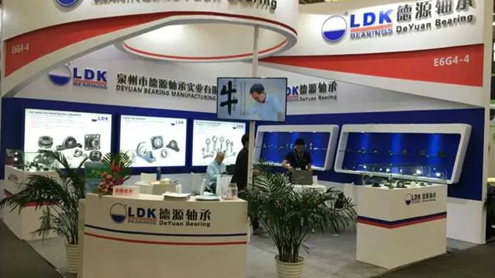
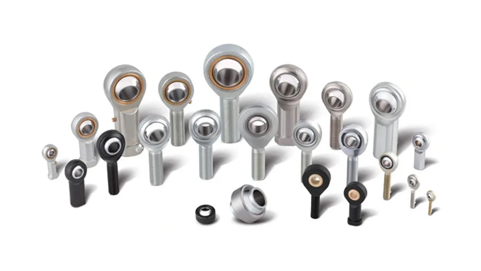
LDK ball bearing units consist of inserts and housings,based on the methods of mounting the units to shafts, they can be divided into four types:the setscrew locking type,the adapter sleeve locking type,the eccentric locking collar type and the concentric locking collar type.
The housings have five types:Cast gray or ductile iron housings,pressed steel housings,thermoplastic housings,stainless steel housings and Zinc alloy die casting housings.
Spherical outside surface self-aligning ball bearing units are compact in design with perfect sealing devices. All LDK ball bearing units have contact-type seals at both sides.The seals will vary according to the different types of bearings.By selecting the sealing devices,which is most suitable to the application and working condition,long bearing life can be guaranteed.
Sealing Devices:
(Table 1)
J type seal
| Synthetic rubber is baked to the core piece.It is inserted into the groove of the outer ring and then fitted on the inner ring outer diameter,thus it has low friction,high property in oil resistance and good mechanical stability. |
H type seal
| This type of seal comprises a pressed steel seal featuring a vulcanized synthetic rubber sealing lip embedded within. This seal creates a minute gap with the outer diameter of the inner ring, effectively shielding against dust, sand, or other potential contaminants, thereby ensuring efficient protection. |
| Oil seal is fixed in the outer ring inner diameter groove,and the slinger is set at the inner ring outer surface.In addition,the simultaneous revolution with inner ring generate the wind pressure for dust-proof property.This constitutes the ideal labyrinth,so effective dust-proof property can be guaranteed. |
| The new design of "Step"slinger not only reinforces the rigidity of slinger but also increase the interior space between slinger and seal.This lead to less friction between slinger and seal when bearing facing pressure and therefore enable the bearing having a better sealing performance than ''flat'' slinger design. |
L3 type seal
| This type consists of a metal cap and synthetic rubber seal,which are baked together to form a single seal.Seal lips have enough tightening allowance.In addition,the lip layers are of triple construction and outside matters,such as dust,water,etc.,are shut out.This sealing system shows its outstanding function under bad conditions. |
F type seal
| This type encloses a synthetic rubber washer between two metal caps.Due to the three pieces design with protective outer shroud,the sealing is excellent. |
The spherical outside ball bearing inserts are sealed at both sides.The internal structure dimensions,chromium bearing steel balls and retainers are same as those of the deep groove ball bearings.
LDK'S insert ball bearings are available with material of Chromium steel and stainless steel.
2.1.1 Gcr15 Chromium Bearing Inserts
The bearing rings and balls are made of GCr15 chromium bearing steel of which the chemical composition are shown in table 2.
(Table 2)
C | Cr | Si | Mn | S | P |
0.95-1.05 | 1.40-1.50 | 0.15-0.35 | 0.25-0.45 | ≤0.025 | ≤0.025 |
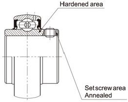
The Rockwell hardness forbearing rings are HRC59-65,for balls are HRC61-66,with high wear resistance and contact fatigue strength.For the inner ring of the setscrews type bearings,the hardness of the setscrews hole zone on the extended ends are less than HRC50 after annealing(CSB,SER,SB,CSB series).
The inner rings of setscrews type bearings are special heat treated by the induction heating method.Therefore, the raceway of the inner ring is hardened completely through the ring, while the setscrews hole zone on the extended ends of the inner rings are softened (as indicated in drawing).
The bearings have two hardened setscrews with threads which are installed in the soft extension of the inner ring, thread contact is thereby attained for maximum holding power,since they can be sufficiently tightened without causing inner ring cracking.
This special heat treatment ensures the most efficient bearing performance and prevents the setscrews from loosening during operation.
2.1.2 Material of Stainless Steel Bearing Inserts
The bearing rings and balls are made of SUS440 equivalent stainless steel of which the chemical composition are shown in Table 3.
(Table 3)
Material | C | Si | Mn | P | S | Cr | Mo | Ni | Cu | Ni+Cu |
G95Cr18 | 0.90~1.00 | ≤0.80 | ≤0.80 | ≤0.035 | ≤0.030 | 17~19.00 | ≤0.03 | ≤0.25 | ≤0.50 | |
G102Cr18Mo | 0.95~1.10 | ≤0.80 | ≤0.80 | ≤0.035 | ≤0.030 | 16~18.00 | 0.40~0.70 | ≤0.03 | ≤0.28 | ≤0.50 |
G65Cr14Mo | 0.60~0.70 | ≤0.80 | ≤0.80 | ≤0.035 | ≤0.030 | 13~15.00 | 0.50~0.80 | ≤0.03 | ≤0.25 | ≤0.50 |
For material of components of stainless steel insert bearings, please see table 4.
(Table 4)
DESCRIPTION | MATERAIALS |
INNER &OUT RINGS | G95Cr18,G102Cr18Mo,G65Cr14Mo |
BALLS | G95Cr18,G102Cr18Mo,G65Cr14Mo |
SETSCREW | SUS304 |
RETAINER | SUS304 |
SLINGER & FRAME | SUS304+Silicone RubberSeal |
GREASE (please check with us for details) | H1 approved food grease or Industry grease |
OPERATING TEPERATURE | -20C°~+120C° |
2.2.1 Outer Rings Toleraces
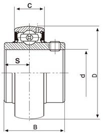
The outer rings tolerances,which are shown in Table 5,are the same as those for deep groove bearings.
Table 5. Outer rings tolerances (μ m)
D (mm) | △Dmp | Kea | ||
over | incl | high | low | max |
30 | 50 | 0 | -11 | 20 |
50 | 80 | 0 | -13 | 25 |
80 | 120 | 0 | -15 | 35 |
120 | 150 | 0 | -18 | 40 |
150 | 180 | 0 | -25 | 45 |
180 | 250 | 0 | -30 | 50 |
250 | 315 | 0 | -35 | 60 |
Notes:
△Dmp=the deviation of a single plane mean
outside diameter of the outer ring.
Kea=Radial run out of assembled bearing outer ring.
D=Nominal outer ring outside diameter.
2.2.2 Inner Rings Tolerances
The inner rings tolerances are different from those of deep groove bearings.The values are shown in Table 6 and Table 7.
1)Tolerances for cylindrical bore bearing inner rings
Table 6. Cylindrical bore inner rings tolerances (μm)
d (mm) | △dmp | Kia | △Bs | |||
over | incl. | high | low | max. | high | low |
10 | 18 | +15 | 0 | 12 | 0 | -120 |
18 | 30 | +18 | 0 | 15 | 0 | -120 |
30 | 50 | +21 | 0 | 18 | 0 | -120 |
50 | 80 | +24 | 0 | 22 | 0 | -150 |
80 | 120 | +28 | 0 | 28 | 0 | -200 |
120 | 180 | +33 | 0 | 35 | 0 | -250 |
Notes:
d=Nominal bore diameter
△dmp=The deviation of a single plane mean bore diameter of the inner rings
Kia=Radial run out of assembled bearing inner ring
△Bs=The deviation of a single width of inner ring
2)Tapered Bore Inner Rings Tolerances
Table 7.Tolerances on inner rings of tapered bore bearings (μm)
d (mm) | △dmp | △dimp-△dmp | |||
over | incl | high | low | max | min |
10 | 18 | +27 | 0 | +18 | 0 |
18 | 30 | +33 | 0 | +21 | 0 |
30 | 50 | +39 | 0 | +25 | 0 |
50 | 80 | +46 | 0 | +30 | 0 |
80 | 120 | +54 | 0 | +35 | 0 |
120 | 150 | +63 | 0 | +40 | 0 |
Notes:
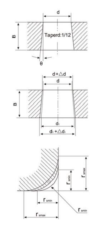
d=Nominal bore diameter
d₁=Theoretical diameter of larger end of tapered bore d₁ is obtained by following formula: is obtained by following formula: d=d+0.083333 B
B1=Nominal inner ring width
θ=The nominal taper angle=2° 23' 9.4"=2.38594°
△dmp =Variation of tolerance of average bore diameter in plane at theoretical small end of tapered bore.
△d1mp=Variation of tolerance of average bore diameter in plane at theoretical large end of tapered bore.
△d1mp -△dmp =Variation of tolerance of average bore diameter in planes between theoretical small and large end of tapered bore.
2.2.3 Chamfer Dimensions for Inner Ring
Table 8 Chamfer dimension limits (mm)
Nominal chamfer dimension r(min) | Radial direction | Axial direction | Chamfer Radius of Shaft f(max.) |
max. | max. | ||
1 | 1.5 | 3 | 1 |
1.5 | 2.3 | 4 | 1.5 |
2 | 3 | 4.5 | 2 |
2.5 | 3.8 | 6 | 2.5 |
3 | 5 | 8 | 3 |
2.2.4 Tolerances for Distance ''S'' From Center Line of Outer Ring to Side of Inner Ring
Tolerances for distance ''S'' between the radial plane passing through center of spherical surface of outer ring and a side of inner ring are shown in table 9.
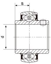
Table 9
Nominal bore diameter d(mm) | Deviation △S | |
over | incl. | |
-- | 50 | ±200 |
50 | 80 | ±250 |
80 | 120 | ±300 |
The radial internal clearance for the spherical outside surface ball bearings is usually greater than that of the same sizes of deep groove ball bearings.The clearance for the cylindrical bore bearings is shown in Table 10, while the clearance for the tapered bore bearings is shown in Table 11.
table 10. Radial internal clearance of cylindrical bore bearings (μm)
Nominal bore diameter d (mm | Clearance(with setscrews or eccentric locking collars) | ||||||
C2 | Basic group | C3 | |||||
> | - | min | max. | min | max. | min | max. |
10 | 18 | 3 | 18 | 10 | 25 | 18 | 33 |
18 | 24 | 5 | 20 | 12 | 28 | 20 | 36 |
24 | 30 | 5 | 20 | 12 | 28 | 23 | 41 |
30 | 40 | 6 | 20 | 13 | 33 | 28 | 46 |
40 | 50 | 6 | 23 | 14 | 36 | 30 | 51 |
50 | 65 | 8 | 28 | 18 | 43 | 38 | 61 |
65 | 80 | 10 | 30 | 20 | 51 | 46 | 71 |
80 | 100 | 12 | 36 | 24 | 58 | 53 | 84 |
100 | 120 | 15 | 41 | 28 | 66 | 61 | 97 |
120 | 140 | 18 | 48 | 33 | 81 | 71 | 114 |
Table 11. Radial internal clearance of tapered bore bearings (μm)
Nominal bore diameter d (mm) | Clearance with tapered bore (UK200,UK300) | ||||||
C2 | Basic group | C3 | |||||
> | - | min. | max | min | max | min | max. |
10 | 18 | 10 | 25 | 18 | 33 | 25 | 45 |
18 | 24 | 12 | 28 | AF | 36 | 28 | 48 |
24 | 30 | 12 | 28 | 23 | 41 | 30 | 53 |
30 | 40 | 13 | 33 | 28 | 46 | 40 | 64 |
40 | 50 | 14 | 36 | 30 | 51 | 45 | 73 |
50 | 65 | 18 | 43 | 38 | 61 | 55 | 90 |
65 | 80 | 20 | 51 | 46 | 71 | 65 | 105 |
80 | 100 | 24 | 58 | 53 | 84 | 75 | 120 |
100 | 120 | 28 | 66 | 61 | 97 | 90 | 140 |
120 | 140 | 33 | 81 | 71 | 114 | 105 | 160 |
Notes: When the internal clearance of a bearing is measured,deformation occurs under loading,Therefore, to obtain the measuring value clearance,add the below correction clearance (see Table 12)to the radial clearance above.
table 12.
Bore dia. d(mm) | Measuring oad | Radial clearance correction amount(μm) | |||
> | - | (N) | C₂ | Normal | C₃ |
10 | 18 | 25 | 4 | 4 | 5 |
18 | 30 | 50 | 5 | 5 | 6 |
30 | 50 | 50 | 4 | 4 | 5 |
50 | 80 | 100 | 6 | 7 | 7 |
80 | 100 | 150 | 8 | 8 | 9 |
LDK's bearing housings are available with cast gray iron, cast ductile iron, Stainless steel, Thermoplastic, Stamped steel and Zinc Alloy steel.
3.1.1 Material for Cast Iron Housings
The material for cast iron housing is HT200(gray iron)and QT400/QT450(ductile iron)of which the mechanical properties are shown in Table 13.
Table 13-(1).
No. | Major wall thickness of casting piece (mm) | Strain minimum stress min (σb/Mpa) | Hardness (HBS) |
HT200 | >2.5-10 >10-20 >20-30 >30-50 | 220 195 170 160 | 157-236 148-222 134-200 128-192 |
Table 13-(2).
No. | Tensile strength (σb/Mpa) | Yield strength (σ0.2/Mpa) | Hardness (HBS) |
min | For reference | ||
QT400 | 400 | 250 | 130-180 |
QT450 | 450 | 310 | 160-210 |
3.1.2 Material of Stainless Steel Housings
The material for Stainless Steel Housing is SUS304 Stainless steel of which the chemical composition are shown in following table 14.
Table 14. (%)
C | Si | Mn | P | S | Cr | Ni |
≤0.07 | ≤1.00 | ≤2.00 | ≤0.035 | ≤0.030 | 17.00~19.00 | 8.00~11.00 |
3.1.3 Material of Zinc Alloy Housings
Zinc Alloy Die Casting
3.1.4 Material of Thermoplastic housings
The material for thermoplastic housing is mainly reinforced PBT or PA polymer.PP polymer is used for end covers.
3.1.5 Material of stamped steel
Cold rolled steel sheet,surface with electroplating treatment.
Table 15. Tolerances on spherical inside diameter of housing (μm)
Nominal spherical inside diameter (mm) | H7 | J7 | K7 | ||||
Dam | Dam | Dam | |||||
Over | Incl. | High | Low | High | Low | High | Low |
30 | 50 | 25 | 0 | 14 | -11 | 7 | -18 |
50 | 80 | 30 | 0 | 18 | -12 | 9 | -21 |
80 | 120 | 35 | 0 | 22 | -13 | 10 | -25 |
120 | 180 | 40 | 0 | 26 | -14 | 12 | -28 |
180 | 250 | 46 | 0 | 30 | -16 | 13 | -33 |
250 | 315 | 52 | 0 | 36 | -16 | 16 | -36 |
Notes
Dam=(Da max+Da min)/2
Damax_Da maximum measured value of Da.
Damix_Da minimum measured value of Da.
Dimensional tolerances for spherical inside diameter of housing are classified into H7 clearance fit, K7 for interference fit and J7 for intermediate fit between H7 and K7.
When H7 fit is applied,the self-aligning bearings are equipped with locking-pins.
3.2.1 The fits between inserts and the housings
Under normal conditions,the fit between insert and housing,which can be supplied by us,is listed as follows: Table 16.
Housings No. | 201-209 305-309 X05-X09 | 210-220 310-328 X10-X20 |
The fits between inserts and the housings | H7 J7 | J7 |
If not specified,J7 fit will be standard fit for LDK mounted ball bearing units.If other fit or starting torque requirement is required,please check with our sales.
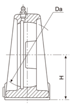
3.2.2 Tolerances for Pillow Block Housings Center Height
Table 17. (mm)
Housings NO | Deviations △H | |||
Pillow Block | Pedestal Base Pillow Block | Tap Base Pillow Block | High | Low |
P201-P210 P305-P310 AK201-AK210 PE201-PE210 PX05-PX09 LP201-LP208 |
PH201-PH210 | PA201-PA210 PG201-PG210 PW201-PW210 PA201A-PA210A |
+0.15 |
-0.15 |
P211-P218 PE211-PE215 P311-P319 AK211-AK215 PX10-PX17 |
PH211-PH212 |
PA211-PA212 |
+0.20 |
-0.20 |
P220 P320-P328 | +0.30 | -0.30 | ||
3.2.3 Tolerances for Flange Type Housings
Tolerances for Flange Type Housings are shown in Table 18.

Table 18. (mm)
Housing No. | Deviations △A₂ | Tolerances of position for mouting bolt holes | |||||||
F,FU | F,FL | FL,FT,FLU | FX,FLX | LF | LFTC | FD,FW | high | low | X≤ |
203 204 205 206 | --- --- 305 306 | 203 204 205 206 | --- --- X05 X06 X06 | 203 204 205 206 | 203 204 205 206 | 203 204 205 206 |
+0.52 |
-0.52 |
0.6 |
207 208 209 210 | 307 308 309 310 | 207 208 209 210 | X07 X08 X09 X10 | 207 208 | 207 208 | 207 208 |
+0.52 |
-0.52 |
0.8 |
211 212 213 214 215 216 217 218 | 311 312 313 314 315 316 317 318 | 211 212 213 214 215 216 217 218 | X11 X12 X13 X14 X15 X16 X17 X18 |
+0.62 |
-0.62 |
0.8 | |||
319 320 322 324 326 328 | X20 |
+0.62 |
-0.62 |
1.0 | |||||
3.2.4 PFTD, FCT (RFB)
*Re-lube. Type PFTD, FCT Housings Available too.
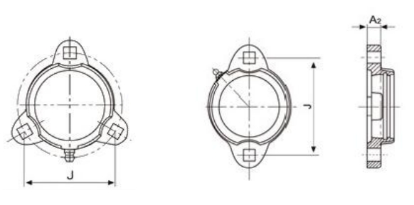
(mm)
Housing NO | Deviations △A₂ | Tolerances of position for mouting boltholes | ||
PFTD | FCT/RFB | High | Low | △J |
203-206 | 203-206 | +0.52 | -0.52 | ±0.70 |
207 | 207 | ±0.80 | ||
3.2.5 Tolerances for flange cartridge type housings
Tolerances for flange cartridge type housings are shown in Table 19.

Table 19. (mm)
Housing No. | Deviations △A₂ | Deviations △D₁ | Radial runout of spigot joint | Tolerances of position for mounting bolt holes | |||
FC | FS | high | low | high | low | t≤ | X≤ |
203 204 205 206 |
305 306 |
+0.52 |
-0.52 |
0 |
-0.046 |
0.20 |
0.60 |
207 208 209 210 | 307 308 309 310 |
0 |
-0.054 |
0.80 | |||
211 212 213 214 215 216 217 | 311 312 313 314 315 316 317 |
+0.62 |
-0.62 |
0 |
-0.063 |
0.30 |
0.80 |
218 | 318 | +0.62 | -0.62 | 0 | -0.072 | 0.30 | 0.80 |
319 320 322 324 326 328 |
+0.62 |
-0.62 |
0 |
-0.072 |
0.40 |
1.00 | |
3.2.6 Tolerances for special type flange units
Tolerances for special type flange units are shown in Table 20.
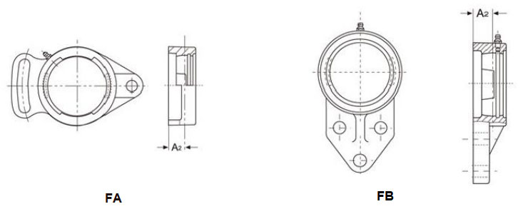
(mm)
Housings No. | Deviations △A₂ | ||
FA | FB | High | Low |
203-210 | 203-210 | +0.52 | -0.52 |
211-213 | 211-213 | +0.62 | -0.62 |
3.2.7 Tolerances for Cartridge Type Housings
Tolerances for Cartridge Type Housings are shown in Table 21.
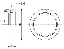
Table 21. (mm)
Housing No. | Deviation ofoutside diameter △L | Radial runout of spigot joint | Deviation △A | |||||
C200 | C300 | |||||||
C | C | high | low | high | loW | t≤ | high | low |
203-205 | 305 |
0 | -0.030 |
0 | -0.035 |
0.20 |
+0.20 |
-0.20 |
206-208 | 306-308 | -0.035 | ||||||
209-210 | 309-310 | -0.040 | ||||||
211-213 | 311-314 | -0.040 | 0.30 | +0.25 | -0.25 | |||
315-318 | -0.046 | |||||||
319 |
0.40 |
+0.30 |
-0.30 | |||||
320-322 | -0.052 | |||||||
324-328 | ||||||||
3.2.8 Tolerances for Take-up Type Housings
Tolerances for Take-up type housings are shown in Table 22.
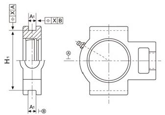
Table 22. (mm)
Housings No. | Deviations △A1 | Deviations △H1 | Parallelism of sliding slot | |||||
T200 | ST200 | TX | T300 | high | low | high | low | X≤ |
203-210 | 203-210 | 05-09 | 305-310 | +0.5 | -0.25 | +0.25 | -0.25 | 0.50 |
211-218 | 211-218 | 10-17 | 311-318 | +1.0 | -0.25 | +0.25 | -0.25 | 0.60 |
319-322 | +1.0 | -0.25 | +0.25 | -0.25 | 0.70 | |||
324-328 | +1.0 | -0.25 | +0.25 | -0.25 | 0.80 | |||
